- Boundary Conditions
In order to calculate the displacement and deflection of the skewed plate different meshes of plate are simulated using different shell element model (SC8R and SC 13 R) and a concentrated force of 600 N is applied at the right top corner opposite to z=axis and it is observed that there is no deflection occur at the bottom edge of the plate. The size of mesh for both the models is selected as 100 mm including the (STR 13) shell element model and more improved and accurate (STR 8) shell model, the results of both approaches are attached in figure 4 below.
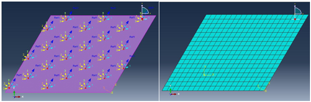
Figure 4: Boundary Conditions and mesh analysis
- Results
There are two different conventions used for the analysis of skewed sandwich plate the conventional shell model and the continuum shell model the result of both parts is sequentially displayed below.
- Conventional Model
Following are the parameters of conventional model.
Size of mesh = 100
Total number of nodes = 378
Total number of elements = 680
Type of element is (STR13)
Maximum deflection = 13.4
The below table shows the maximum principal stress with its corresponding ply number.
| Ply number | Maximum principal stress |
| 1 | 1.178 |
| 2 | 7.537 |
| 3 | 7.3 6 e-17 |
| 4 | 58.573 |
| 5 | 11.332 |
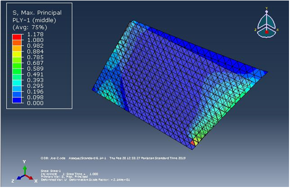
Figure 5: Max-Principal (Ply-1)
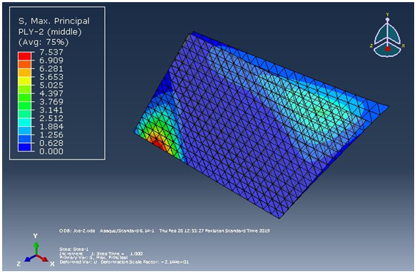
Figure 6: Max-Principal (Ply-2)
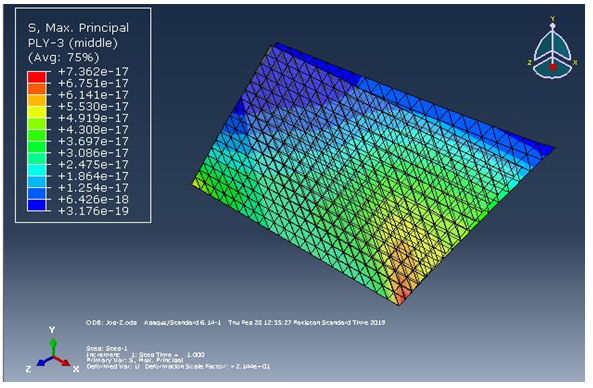
Figure 7: Max-Principal (Ply-3)
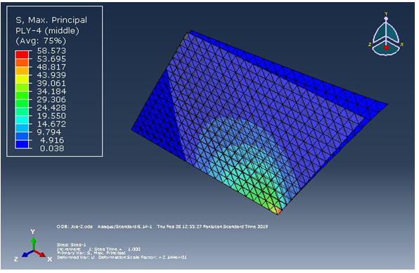
Figure 8: Max-Principal (Ply-4)
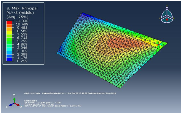
Figure 9: Max-Principal (Ply-5)
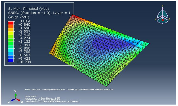
Figure 10: Max-Principal (Layer-1)
- Continuum Shell Model (Improved Model)
Following are the parameters of continuum shell model.
Size of mesh = 100
Total number of nodes = 756
Total number of elements = 340
Type of element is (SC8R)
Maximum deflection = 10.887
The below table shows the maximum principal stress with its corresponding ply number of the improved continuum shell model.
| Ply number | Maximum principal stress |
| 1 | 0.931 |
| 2 | 0.382 |
| 3 | 1.207e-3 |
| 4 | 0.430 |
| 5 | 0.791 |
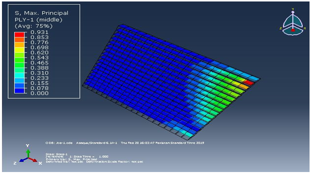
Figure 11: Max-Principal (Ply-1)
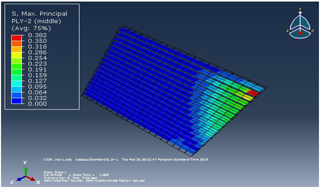
Figure 12: Max-Principal (Ply-2)
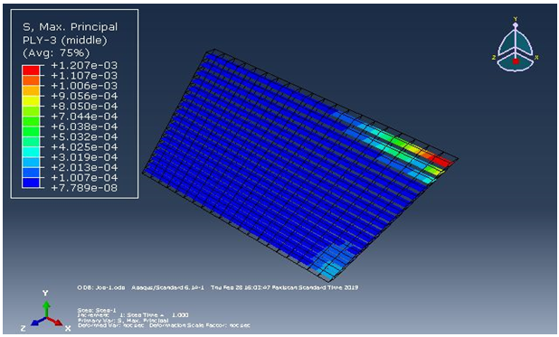
Figure 13: Max-Principal (Ply-3)
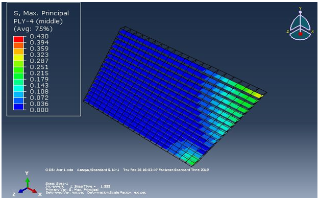
Figure 14: Max-Principal (Ply-4)
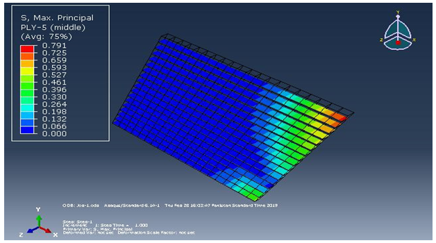
Figure 15: Max-Principal (Ply-5)
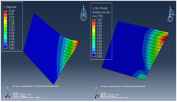
Figure 16: U-Magnitude Figure 17: Max-Principal
- Conclusion
The conclusion is based on the data extracted from two different approaches the conventional shell model and the continuum shell model the deflection of the skewed sandwich plate is observed using shell element STR 13 a concentrated force of 600 N is applied at upper right corner and the maximum displacement is observed is 13.4 mm while we got a deflection of 10.883 mm using the continuum shell model.
The tensile strength of the skewed sandwich plate is also observed. Using the conventional shell model we get a maximum principal stress of 10.284 MPa. Using the continuum shell model we get a maximum principal stress of 1.007 MPa. This particular observation shows us that the accurate model for observation of force is continuum shell model.......
This is just a sample partical work. Please place the order on the website to get your own originally done case solution.
Related Case Solutions & Analyses:
 Regulatory Uncertainty and Corporate Responses to Environmental Protection in China
 SecondMarket – Providing Liquidity for Shareholders of Privately Held iContact
 Systems Infrastructure at Google (B)
 Bank of America-Merrill Lynch
 Belmont Industries Inc. (B)
 ZipCar
 1366 Technologies
 Marketing Nissan Micra & Tata Nano Using Social Media
 MANAGEMENT REPORT ON BUSINESS RUNNING CASE