Material Properties
The material used in this following exercise for the lamination is carbon/epoxy T 300/5208. According to the brief document (see in Table-1 and Table-2 in Appendix) the lamination properties of this particular material is,
These properties can be seen below,
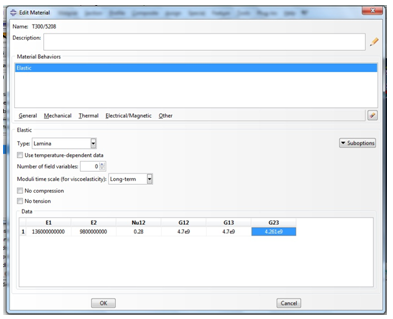
Figure 1 lamina settings
4 Geometry
The geometry of the cylindrical panel depends upon the student ID and since the last 5 numbers of the ID is 93670 S1 is taken as 9, S2 = 36 and S3 is taken as 90, the radius of the circle is calculated to be 136 and the length of the panel is calculated to be 270, all the calculations are shown in section 6.
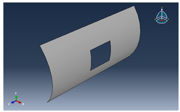
Figure 2 Design
The lamination is also done using the angles in the brief document, the below picture shows the work,
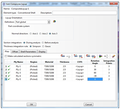
Figure 3 layup
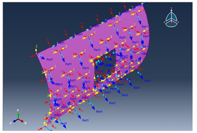
Figure 4 The lamination Layup
5 Boundary Conditions
The boundary conditions are taken to be simple that is E 1, E 2 and E 3 all equal to 0. That can be seen below,
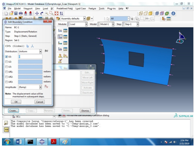
Figure 5 Boundary condition 1
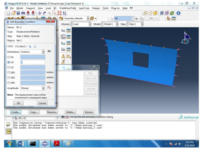
Figure 6 Boundary condition 2
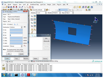
Figure 7 Boundary condition 3
For the buckling analysis the following boundary conditions are used,
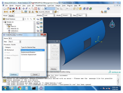
Figure 8 Buckling analysis
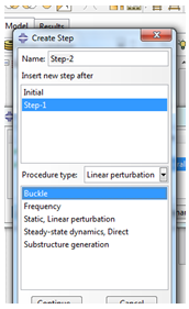
Figure 9 Buckle Selection
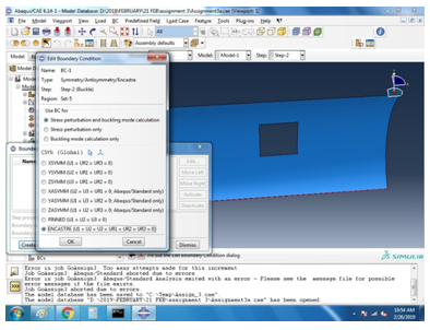
Figure 10 Boundary setting
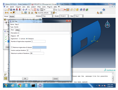
Figure 11 variables for buckle analysis selection
6 Loads
The loads applied to the sides of the panels is selected to be 0.15 N/mm as told.
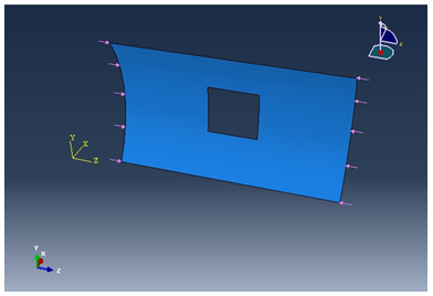
Figure 12 Load at 0.15 N/mm
7 Detailed Calculations
Calculations of geometry:
Given: S1 = 9, S2 = 36, S3 = 70
In XY-plane:
In Z-direction:
For this shell model, the result of stress as shown in the following:
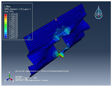
Figure 13 stress after pressure applied
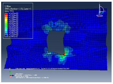
Figure 14 stress after pressure applied another angle
The result of displacement as shown in the following:
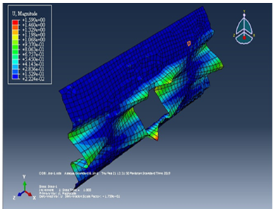
Figure 15 displacement after pressure applied
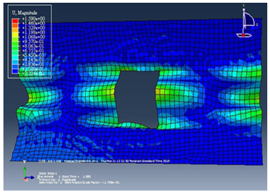
Figure 16 displacement after pressure applied another angle
Buckle analysis Solution:
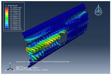
Figure 17 Buckle analysis solution
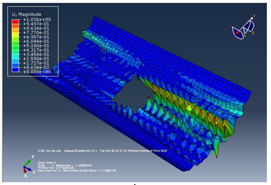
Figure 18 Another view of the result
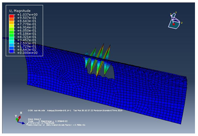
Figure 19 Lamina 2 result
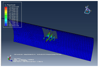
Figure 20 Lamina 3 result
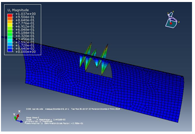
Figure 21 lamina 4 result
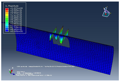
Figure 22 lamina 1 and 5 result
8 Conclusion
The results above are, using the geometry of own design, the maximum stress at the panel is found to be 1470 N/mm^2. The maximum displacement at the panel is found to be 1.59 mm, figure 1 shows the material properties of the designed structureand basics characteristics of the designed structure, the design structure is analyzed with extensive load on each side to observe change in shape or deformity in the cylindrical panel with rectangular cutout. The above designed structure is tested under three different boundary conditions as shown in figure 5,6 and 7 it is observed from the simulations that the cylindrical panel can bear a maximum load of 0.15 N/mm because after applying external pressure a change in shape is observed at the outer structure and in the inner cut out rectangle which can be clearly observed in figure 9 and 10, the four different figures 9, 10, 11 and 12 shows four different points where the external pressure is applied and it is observed that maximum deformity occur when an external pressure is applied from the upper right corner of the designed cylinder.
9 Appendix
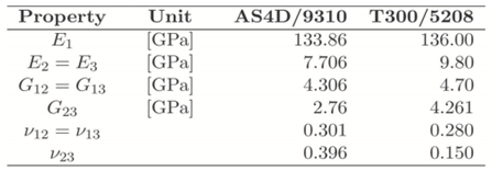
Table-1 Material Properties of unidirectional carbon/epoxy composites
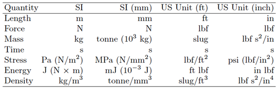
Table-2 Consistent sets of units
Related Case Solutions & Analyses:
 Plans versus Politics: New Orleans after Katrina
 House of Tata: Acquiring a Global Footprint
 Sandvik Coromant Recycling Concept
 Economics Final
 CASE ANALYSIS: USEC INC
 Bloomberg Sports